
BEP CZone Switching -- Progress = 2%
SKU: CZone digital switch
Manufacturer: BEP Marine
Quick overview
- CZone module based digital marine switching.
- Scalable for any size boat
- Automate controls with PC based program.
- Simplify circuits .
Digital Marine Switching System
BEP CZone
Marine Power Distribution is really starting to shine, and BEP is making some substantial footprints with it's high-tech marine power distribution system called the CZone. The schematic you see to the left is my custom designed layout for the Osprey project boat.
I wanted to integrate all of my digital switching controls and have complete control over the switching system in multiple ways; via the BEP 4.3'' dash mounted screen, through the Lowrance HDS 12 touch unit, and by way of standard toggle switches, and of course, I wanted a failsafe feature, which BEP includes a jumper in each module to bypass any circuit switches, thus enabling direct turn on/off.
Let's take a look at the digital marine switching system in depth and see what it offers. The first thing you'll want to determine is where to mount the batteries, battery switches, and the rest of the BEP components that run the system. It's always best to locate as many core components as close to the batteries as you can to save on long cable runs, drops in voltage, etc. In my case, the Osprey comes with a nice storage floor box, bait well, cooler, whatever you want to call it. Personally, I see no use for it in those aspects because everyone usually fishes off the aft, so going for bait and asking everyone to move just isn't worth the time. This boat has plenty of forward storage anyway so I decided to use this.
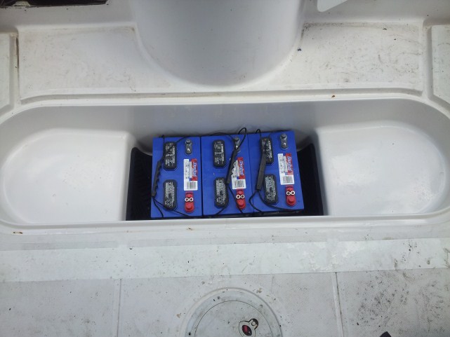 Three 29D batteries fit perfectly in the center well area, and the slopped bottom allows any possible water to drain from the battery area into the hull. I lined the bottom with a thick rubber floor mat and cut a small area back where it covered the drain hole. Two slopped shelves on either side made for a great place to mount the BEP components. The compartment will be pretty watertight, but with the slopes and the drain, any water that may intrude shouldn't be an issue.
Battery Configuration: In the power distribution schematic above, you'll see 3 batteries, a port, starboard, and one house battery. At the time of designing this, I intended on putting two 150 outboards on, but since then decided to go with a single 250. I am only using one start battery, and two house batteries being that the house load can extend upwards of 250 amps if everything were running simultaneously. Of course, that won't be the case, but the house load will require the most demand on the system, so I ran both batteries in parallel.
Battery Switches: This is were the magic starts to take place. Long gone are the days of opening the hatch and turning the battery selector to "1," "2," or "All." BEP has designed some really nice motorized battery switches and an emergency parallel switch that do more than just battery switching. One of the great benefits that drew me to this system was the parallel feature via remote switch. Should your start battery go dead, it's as simple as engaging the emergency parallel switch, which then combines all the batteries from the house side and the start battery to give you ample starting power, in addition to a slick voltage sensing aspect that automatically charges batteries, and can even isolate a low battery so as not to drain it further while your engines charging system is off. What all this means in a nut shell is that you have a watchful eye insuring you don't kill your batteries and leave yourself stranded, while it properly charges and maintains your battery while your engine is running and charging. As you may notice, I removed two of the motorized battery switches, as they were no longer needed for this new design. One switch is for the parallel house batteries, as they act as one, and the other is for the start battery. The remaining yellow switch is the emergency parallel switch. Mixed in with the switches is a surge protector for the system, which hooks to the house side load and is fused.
Please ignore the mess in this photo...I'll take a new one after all is mounted and dressed in. I just measured and terminated the cables and mounted the components. I installed the emergency parallel switch in this same area using a modified NMEA box (gray box). Being that I didn't see this switch being used very much, I didn't want to clutter my dash with it, as I have enough going on there. There isn't much to it, as the motorized switches connect to the keyed breaker panel, which I'll explain next. In this photo, on the bottom is a dark gray box mounted vertical. This is a 300 amp blade fuse for the house load, as you can also see in the previous image. The other dark gray box to the left of the image is a shunt, which is used to get an accurate battery voltage reading.
INFO
What to know about the person that wrote this review? Click the "Reviewer Credentials" tab
REVIEWER CREDENTIALS
Allen Applegarth is a published author and outdoor writer. His books include Florida Fishing, and Florida Inshore Angler. He's an avid boater and angler with over 30 years of experience. In addition to being a writer, Allen is also a product designer and experienced electronics tech, with a few medical devices designed and implemented under his accomplishments . He owns and operates a communications company that provides the following services:
Cell Tower: Testing, Installation, Audits
Microwave: Design, Installation
Satellite: Large Infrastructure Head End Design & Installation
DAS Systems: Design and Installation; passive, active, hybrid
Fiber Optic: Boring, Installation -FTTC, FTTH, FTTD, Backbone
Network Office Cabling & Design, RFID, Automation, WiFI, CCTV
Feasibility Studies:
Allen has a broad range of skills, and as such, is titled as an "Expert Reviewer" in his respected fields for Review Warehouse. com

CONFIGURATION:
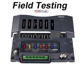
CZone consists of a series of signal interface, switch controllers, and output modules that are programmable by the end user via a NMEA to USB connect made to a computer running the CZone software. The versatility of the CZone swithcing system is nearly limitless for marine applications.
VERSATILITY & SECURITY
CZone is designed for 9-32V systems, features built-in timers, dimmers (including support for halogen lighting), alarms, voltage reducers and load shedding. With safety in mind, CZone™ features a manual bypass. Our No-Single-Failure-Point technology ensures a plug-n-play system that is designed to handle mishaps. If a module i
s damaged, the system will automatically program the replacement module, when it is plugged in. This means any module can be replaced without using high tech service people. Our security features allow custom configurations that can be locked
 Marine Switching